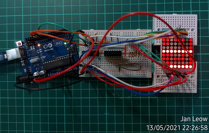
I have been going through the Beginning Arduino text book to learn a bit about this popular microcontroller. I have these various components from the starter kit that I purchased last year during the pandemic lockdown and taking my time to learn about it. During this long weekend holiday, I decided to give the dot matrix sketch a go. Following the Arduino diagram and running the code in the sketch, the display came out randomly and not at all like the textbook. Apparently each manufacturer of the 8×8 Dot Matrix Display has their own way of setting up the pin header configuration.
I searched through the internet and there wasn’t any info about my particular component with the code 1088. The dot matrix has some smudge print at the end of it. It could well be 1088BS. The forum that I checked through didn’t mention the pin headers, but were discussing something else. Then I came across a video about checking the pin headers configuration by yourself.
Well, no choice. It took me a long while to test the pin one by one. All the tedious work came out well and I got the 8×8 dot matrix 1088BS(?) display to work as it should.
The thing about the matrix display, by applying a charge on two pins, you would get the x-y coordinates to light up the LED. However the pin headers are not lined accordingly and seem to be jumping all over in random sequence. The column and row pins are placed on both sides of the dot matrix display. What I have worked out here may or may not be the same for the 1088 or 1088BS components that are out there in the market. So if my diagram didn’t work for you, you would just have to test the pin one by one.
How to go about checking the pin header configuration.
In my case I used the code from the textbook, which showed a square within a square that lighted up and then inverted the light display. I needed that because if the charge was reversed the LED wouldn’t blink, but would stay permanently lit. Which meant I would have to reverse the connection to get it right.
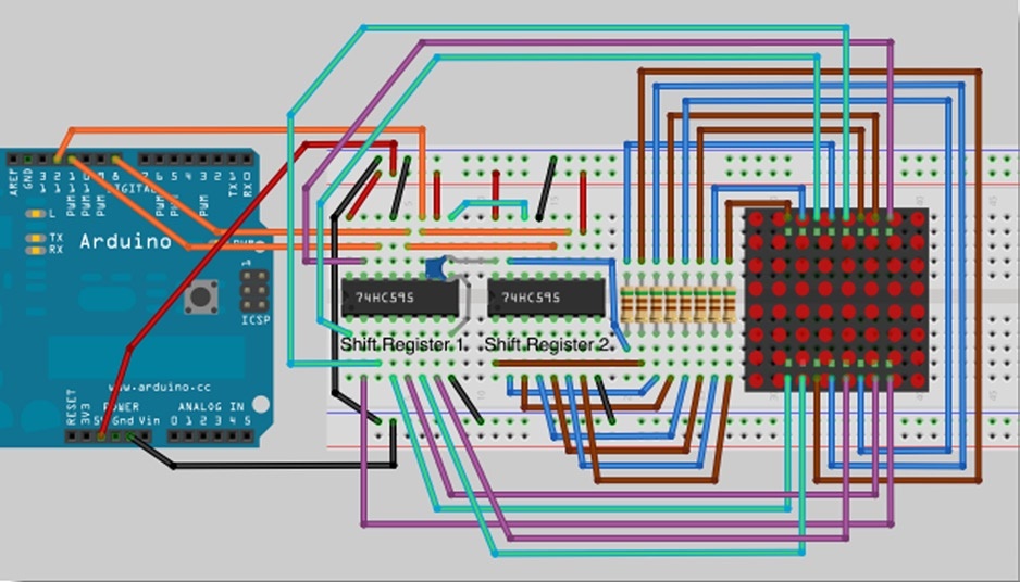
I am using two shift registers 74HC595N, one each to control the row and column section of the 8×8 dot matrix display. First wired up per the textbook diagram, which was rather complicated. Take note the shift registers data output starts from Q0 and ends with Q7. Some sites use connection 1 to 16, but that gets confusing as I didn’t know they were to which shift register. I just kept it simple and call it Shift Reg 1 and Shift Reg 2.

After that, get a piece of paper and sketch out the pin and connections. I used the code C1~C8 for column and R1~R8 for row. As the pins were being tested one by one, The LED would light up. Look for the LED from one of the corners and work your way down for each row and column. I should think there is no correct first corner, so I suppose you could take any corner as your first corner coordinates.
And of course do note down the corresponding connection on the paper sketch, so that you may have a future reference should you need to use the 8×8 dot matrix display.

So here’s the Arduino sketch code for the blinking inverting LED square from the textbook for your checking. Remember, if the LED does not blink, you would need to reverse the connection or find the correct connection.

// Project 19 // LED Dot Matrix Display Basic Animation
// Chapter 7 Pg127 // Beginning Arduino 2nd Ed 2013

//
#include <TimerOne.h> // Install the library first or the code won’t work
int latchPin = 8; //Pin connected to Pin 12 of 74HC595 (Latch)
int clockPin = 12; //Pin connected to Pin 11 of 74HC595 (Clock)
int dataPin = 11; //Pin connected to Pin 14 of 74HC595 (Data)
byte led[8]; // 8 element unsigned integer array to hold the sprite
void setup() {
// set the 3 digital pins to outputs
pinMode(latchPin, OUTPUT);
pinMode(clockPin, OUTPUT);
pinMode(dataPin, OUTPUT);
// Load the binary representation of the image into the array
led[0] = B11111111;
led[1] = B10000001;
led[2] = B10111101;
led[3] = B10100101;
led[4] = B10100101;
led[5] = B10111101;
led[6] = B10000001;
led[7] = B11111111;
// set a timer of length 10000 microseconds (1/100th of a second)
// and attach the screenUpdate function to the interrupt timer
Timer1.initialize(10000);
Timer1.attachInterrupt(screenUpdate);
}

// invert each row of the binary image and wait 1/4 second
void loop() {
for (int i=0; i<8; i++) {
led[i]= ~led[i];
}
delay (250);
}
// Display the image
void screenUpdate() {
byte row = B10000000; // row 1
for (byte k = 0; k < 8; k++) {
shiftOut(dataPin, clockPin, LSBFIRST, led[k] ); // LED array
shiftOut(dataPin, clockPin, LSBFIRST, ~row); // row binary number (active low)
// latch low to high to output data
digitalWrite(latchPin, LOW);
digitalWrite(latchPin, HIGH);
// bitshift right
row = row >> 1;
}
// Turn all rows off until next interrupt
shiftOut(dataPin, clockPin, LSBFIRST, 0);
shiftOut(dataPin, clockPin, LSBFIRST, ~0);
// latch low to high to output data
digitalWrite(latchPin, LOW);
digitalWrite(latchPin, HIGH);
}